OSI Model
Description:
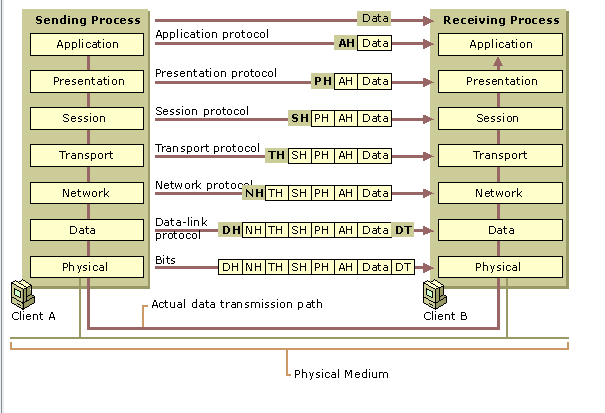
In 1983, the International Standards Organization (ISO) developed a model that would allow the sending and receiving of data between two computers. It works on a layer approach, where each layer is responsible for performing certain functions. In the Open Systems Interconnect model, which allows dissimilar computers to transfer data between themselves, there are SEVEN distinct layers. Data is passed from one layer down to the next lower layer at the sending computer, until its finally transmitted onto the network cable by the Physical Layer. As the data it passed down to a lower layer, it is encapsulated into a larger unit (in effect, each layer adds its own layer information to that which it receives from a higher layer). At the receiving end, the message is passed upwards to the desired layer, and as it passes upwards through each layer, the encapsulation information is stripped off.
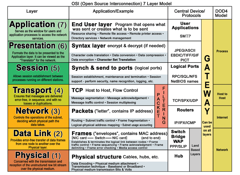
The Seven Layers From Top Down:
-
Application Layer => This layer provides Applications with access to network services.
-
Presentation Layer => This layer determines the format used to exchange data among networked computers.
-
Session Layer => This layer allows two applications to establish, use and disconnect a connection between them called a session. Provides for name recognition and additional functions like security which are needed to allow applications to communicate over the network.
-
Transport Layer => This layer ensures that data is delivered error free, in sequence and with no loss, duplications or corruption. This layer also repackages data by assembling long messages into lots of smaller messages for sending, and repackaging the smaller messages into the original larger message at the receiving end.
-
Network Layer => This layer is responsible for addressing messages and data so they are sent to the correct destination, and for translating logical addresses and names (like a machine name FLAME) into physical addresses. This layer is also responsible for finding a path through the network to the destination computer.
- Data-Link Layer => This layer takes the data frames or messages from the Network Layer and provides for their actual transmission. At the receiving computer, this layer receives the incoming data and sends it to the network layer for handling.
- The Data-Link Layer also provides error-free delivery of data between the two computers by using the physical layer. It does this by packaging the data from the Network Layer into a frame that includes error detection information. At the receiving computer, the Data-Link Layer reads the incoming frame, and generates its own error detection information based on the received frame data. After receiving all of the frame, it then compares its error detection value with that of the incoming frames, and if they match, the frame has been received correctly.
- A Data-Link Layer frame actually consists of two separate parts, the Medium Access Control (MAC) and Logical Link Control Layer (LLC). Example MAC layers are Ethernet 802.3 and Token Ring 802.5. Bridges are an example of devices which works at the MAC layer.
- Physical Layer => This layer controls the transmission of the actual data onto the network cable. It defines the electrical signals, line states and encoding of the data and the connector types used. An example is 10BaseT. Repeaters are an example of devices that work at the Physical Layer. For Ethernet 802.3, the Physical Layer can be represented as: 10Base5, 10Base2, 10BaseT, and 10BaseF.
Comments